The Skyraider Engine
Researching the Wright R-3350 is a tolerably byzantine undertaking. The “Duplex Cyclone” engine was produced in quantity over a long period and for a wide range of applications. According to the National Air and Space Museum website “…a total of 5,656 commercial…and 44,536…military engines…were manufactured…” from 1937 until the late 1950’s. Along the way there were would be any number of configurations, many differing significantly in external aspects important to us modelers.
The first AD’s came out of El Segundo sporting the -8 version, but by the time Douglas got around to the AD-4, they were bolting on higher horsepower -26WA’s with water injection. Vietnam A-1H/J’s, as represented by nearly every last kit on the market regardless of scale, were often fitted with improved versions (dash 28WA, 30WD’s et. al.) which differed in many external details from the earlier models.
For modelers they all primarily look the same, at least as far as the Skyraider is concerned. B-29, Connie, DC-7, C-119 etc. dash models, configuration and installation could vary considerably however and the modeler is poorly served to believe there is any cookie cutter aspect to this important detail.
Even focusing on just the AD/A-1 airframe there could be and often were significant differences. For the miniaturist the primary visual aspects we need to sort out are:
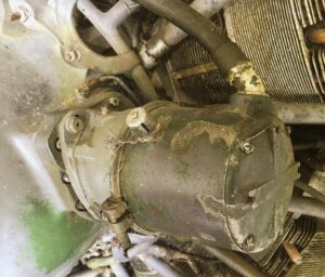
First one must consider time period and airframe dash version. 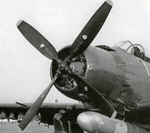 Here we have a perfect example of an early Korean War AD-4. Prior to the later (1951) AD-4B the unique internal baffle/flap system was not present on any Skyraider, thus the engine front is entirely visible. Certainly, once introduced the parts were quickly retrofit to earlier versions, especially in Korea, but prior to the spring of 1951 they were not to be seen. As a side note, it is also apparent from close observation this particular AD's R-3350 is equipped with a High Tension (HT) ignition system. (see explanation further down)
Configuration of the crank case housing along with its associated gear, primarily the prop governor, ignition ring, oil sump assembly and various other fittings could vary significantly depending on engine dash model and production time period, and should be carefully researched if historic technical accuracy is the goal.
As for the internal flap/baffle configuration this can be either easy or hard for the modeler to sort out. In 1/32 scale, the two available kits have the system as separate parts, so they can be easily omitted. In 1/48 and 1/72 all the present kit designs make things considerably more problematic, and rectifying that is beyond the scope of this discussion.
The entire ignition system; distributor and ignition ring configuration, wiring and associated equipment varied tremendously depending on a number of factors. The distributors, the big round cans positioned at approximately 10 and 2 o’clock atop the crankcase, are of extreme importance because the size and configuration of these units identify a particular 3350 as possessing either a low tension (LT) ignition system or high tension (HT) version.
To the modeler the differences are very significant and should be taken into consideration when detailing as discussed below.
Note, while I have observed warbirds with both LT and HT engines installed, as far as I can tell from all the period Navy and Air Force manuals I possess coupled with the extent photo record it appears to me standard AD/A-1 military in-service power plants were equipped with LT ignition systems regardless of dash number.
Having said that, “always” and “never” is very treacherous territory in historical research, as aptly evidenced by the HT equipped Dash-4 in the photo above so I’m definitely not going there; I certainly could be wrong.
That said, period photos do show predominance if not exclusivity of LT system equipped Skyraiders. (For a great discussion of this topic see the Skyraider Owner’s Manual mentioned in the reviews section, p113ff.)
Why is this distinction important for the model builder? Because the size and shape of the distributer units relate directly to how the model engine wiring should be correctly replicated.
Moreover regardless of actual in-service practice, every last Skyraider kit I have ever seen in any scale replicates the large distributer configuration which means that engine is a miniature equipped with a Low Tension (LT) ignition system. The ignition lead configuration between HT and LT are significant and need to be addressed especially in larger scales.
This something I have never yet seen even suggested let alone modeled in any scale representation of this engine. There are some rumblings from Eastern Europe somewhere of a 3D printed item which may be close to the mark, but as of this writing I have not seen it; if it does become available I’ll definitely get one and review it here on the site.
If an aftermarket item is in the pipeline however the fact it has taken anyone in the industry this long to fill the gap (if filled it is to be) brings me back yet again at the doorstep of my overall complaint regarding the universal lackluster level of research regarding this great aircraft.
Model builders, kit designers, alleged “researchers” and aftermarket producers alike have all along seemingly assumed the Wright Duplex Cyclone is something of a P&W R2800 writ large and go on to provide it with generic paired wire harnesses to dress up the front cylinder bank. Having wired up a number of full sized 2800’s in my time, I can testify first hand the big Wright can be a different animal entirely.
Lemme ‘splain…
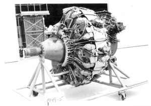 Here we see an example of a B-29 era R3350 equipped with a HT ignition system. Notice there are not 18 but 36 separate leads going from the ignition ring directly to each individual plug.
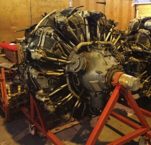 Further on, this is an example of a later R3350 HT system’s distributor configuration; note, they are short, stubby little units and the ignition ring shows a considerable number of lead connection points. (Note: photo from page 162 of the AD/A-1 Skyraider Shop Manual, Haynes Pub.)
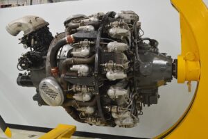
 Here we see a perfect example of a R3500 with the requisite LT system common to many service and all scale Skyraiders. In this case there are only nine ignition ring connections. Following the current flow further we see each lead connects to a “Y” harness a few inches outside the ring providing 2 leads, one for each cylinder.
However, none of these resulting 18 connectors attach to sparkplugs. Rather they feed condenser coils affixed atop each cylinder and it is from these coils two secondary leads power that cylinder’s plugs.
If you check the Project Update here you can see the Zoukei Mura R-3350 converted to a -26W for my 1/32 scale AD-4 project showing the correct wiring run.
Okay, sure, I know all this is not exactly “falling off the log” apparent, but it can and should be, if not replicated, then at least suggested in scale. A little more realistic support, or at the very least a little less misleading “research” from the industry wouldn’t hurt either, but crimminy, with skeighty-thousand more Spitfires, -51’s and -109’s to add to the pile who’s got the time?
In any case, because of the scale and detail level of my 1/32 AD-4 project, (see projects here) I have represented everything as accurately as I can. On the other hand, a Skyraider modeled with the cowling buttoned up and the internal baffle/cooling flaps in place makes the process much simpler since neither the ignition ring nor coil units would be visible. In this case nine “split” wire simulations going back out of sight would be enough to get the job done.
So there; big mystery solved. I guess everybody can sleep better now, nez pas?
Until next time, build long, and prosper.
(Reference: Overhaul Instruction for the Bendix Low Tension, (LT), High Altitude Ignition for the Wright R-3350, Form # L-180-3, 1951)